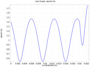
The propagated wave passes the length of the quarter-wave transformer reflecting on the load and passing the load partially. When it reaches the quarter-wave transformer, part of the wave reflects with the reflection coefficient Γ 1, another part of the wave propagate with the coefficient T 1. There is two transmission lines made with blue dashed circles There is a wave that falls from the side of the Z 0. Let’s consider the case of multiple reflection of the waves. The real quarter-wave impedance transformer experiences a variety of reflected and propagated waves. T h e Z i n = Z 0, for the lossless transmission line. And the characteristic impedance of the arbitrary transmission line is Z 1 = Z 0 R. For the β = 2 π λ, l = λ 4, s o Z i n → Z 1 2 R. The input impedance here is Z i n = Z 1 R + j Z 1 tan β l Z 1 + j R tan β l.
The matching transmission lines are assumed to be lossless. The characteristic impedance of the quarter-wave transformer is Z 1, the length is λ 4. Let’s consider the random transmission line with the characteristic impedance Z 0, and the load with resistance R. The quarter-wave impedance transformer is a device that matches the transmission line and the impedance and is shown in Figure 1.


